When a small automotive spiral spring manufacturer sought to improve its production process, Industrial Control (Zeeland, MI, USA; www.industrialcontrol.com) was brought on to develop a machine vision system for gauging. Required measurements for the system include the length of the inner and outer hook ends, the angle of the hooks with respect to each other from spring center, and the radius of the hook end loop.
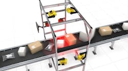
Once a person inserts a part into a tray, a PVD series single-piece part verification sensor array from Banner Engineering (Minneapolis, MN, USA; www.bannerengineering.com) activates the system, signaling an MX-40E vision controller from Datalogic (Bologna, Italy; www.datalogic.com) to activate WLS27 series white LEDs from Banner inside the cabinet. When the tray is inserted into the cabinet, the PVD arrays trigger a greyscale camera, also from Datalogic, to acquire an image of the part after hands are no longer in view.
The camera’s 12 MPixel CMOS sensor pairs with an MTL-24018C-008 large format, bi-telecentric lens from Moritex (Saitama, Japan; www.moritex.com) providing a 240 mm field of view at a 375 mm working distance. A narrow-angle backlight with M12 connector enhances contrast and edges for spring measurement to an accuracy down to 45 μm. Machine vision systems with similar gauging capabilities exist, but this one is designed for larger parts such as piston rings. Furthermore, with its data collection capabilities and optional cloud connectivity, the system addresses Industry 4.0 requirements, while offering real-time error notifications. These features, as well as the extra-large field of view offered, separates it from similar market offerings, suggests Mark Ermatinger, CEO, Industrial Control.
Datalogic IMPACT software running on the controller has a part identification tool called the pattern sorting tool that is used to recognize parts. The tool must be trained on a specific set of patterns that will be recognized on the captured images during operation.
“We program the pattern sort tool, which records all the different parts that might be put into the system,” says Ermatinger. “Parts are loaded into the tray and automatically inspected due to the software’s ability to save these fingerprint-like reference points.”
After measuring all critical dimensions, Banner LEDs illuminate either all green to indicate a passed part or all red to quickly show the operator that the part failed.
“If a part fails, the manufacturer knows a machine is trending out of calibration, and that something is wrong and requires intervention,” says Ermatinger.
The software running on the vision controller sends the image to an FTP server in the controller. Trending software developed by Active Inspection (Grand Rapids, MI, USA; www.activeinspection.com) running on a microcomputer connected to the controller via Ethernet watches for images coming into the FTP server. Images of every part and all the measurements are recorded into the trending software, as well as saved onto a 1 TB hard drive connected to the microcomputer, or onto the cloud, depending on the preference of the customer, according to Ermatinger.
“If the system stores data on the cloud, you can also set different thresholds to send you an alarm on your phone or through e-mail,” he says. “So, if you are a production supervisor and you want to ensure your system stays in spec, you have the option to always be in the loop.”
Designed to collect and organize inspection results for database storage, the data analytics software stores and updates results, providing access to inspection results from the workstation, web browser, or mobile device. For example, manufacturers now can run a histogram for a part and track the production of that part over time. All inspection results are accessible within the software and are customizable to show relevant information.
Going forward, the system will use either Datalogic cameras or 3D scanners from LMI Technologies (Burnaby, BC, Canada; www.lmi3d.com), for customers needing to acquire height and length information at the same time, or in applications where there is a lot of black on black, where there is no contrast and 2D cameras won’t work, explains Ermatinger. Lenses from Opto Engineering (Mantova, Italy; www.opto-e.com) will be available for use in the system, as well.