

An optical drawing is a detailed plan that allows us to manufacture optical components according to a design and given specifications. When optical designers and engineers come up with a design, they condense it in an optical drawing that can be understood by manufacturers anywhere. ISO 10110 is the most popular standard for optical drawing. It describes all optical parts in terms of tolerance and geometric dimension. The image below shows the standard format of an optical drawing.
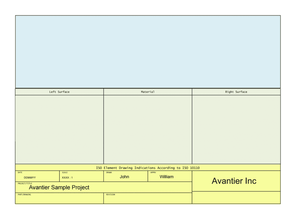
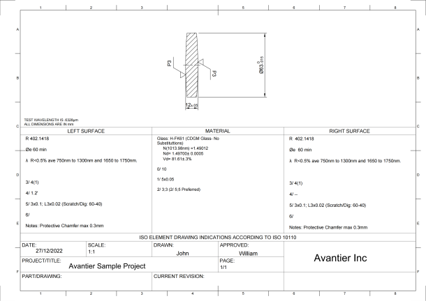
Notice thee main fields. The upper third, shown here in blue, is called the drawing field. Under this the green area is known as the table field, and below this the title field or, alternately, the title block (shown here in yellow). Once an optical drawing is completed, it will look something like this:
Notice the three fields— the drawing field, the table field, and the title field. We’ll look at each of them in turn.
Field I — Drawing Field
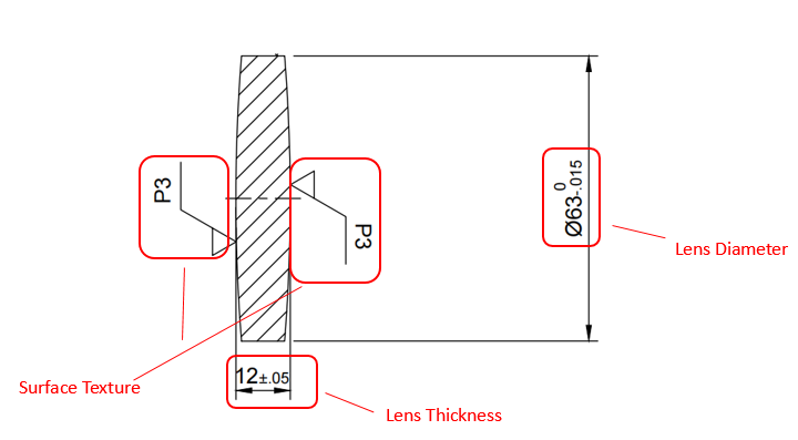
The drawing field contains a sketch or schematic of the optical component or assembly. In the drawing here, we see key information on surface texture, lens thickness, and lens diameter.
P3 means level 3 polished, and describes the surface texture. Surface texture tells us how close to a perfectly flat ideal plane our surface is, and how extensive are the deviations.
63 refers to the lens diameter, the physical measurement of the diameter of the front-most part of the lens
12 refers to the lens thickness, the distance along the optical axis between the two surfaces of the lens
After reviewing the drawing field we know this is a polished bi-convex lens, and we know exactly how large and how thick it is. But there is more we need to know before we begin production. To find this additional information, we look at the table field.
Field 2— Table Field
In our example, the optical component has two optical surfaces, and table field is broken into three subfields. The left subfield refers to the specifications of the left surface, and the right subfield refers to the specifications of the right surface. The middle field refers to the specifications of the material. Surface Specifications:
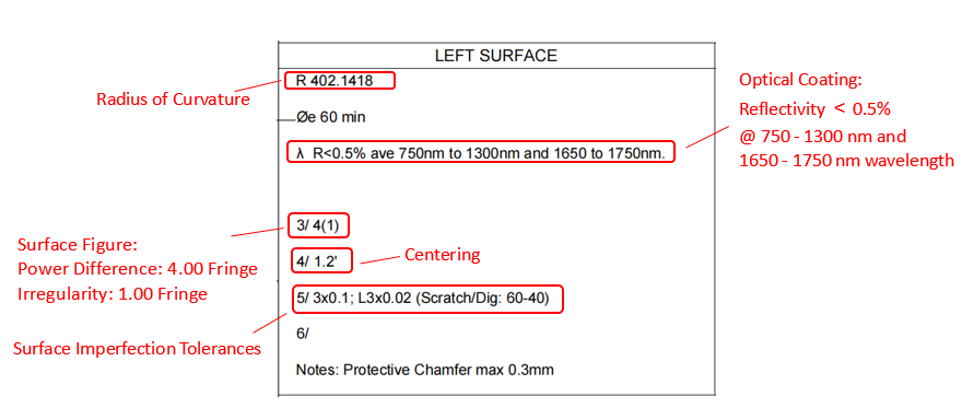
Sometimes designers will indicate “CC” or “CX” after radius of curvature, CC means concave, CX means convex.
Material Specifications:
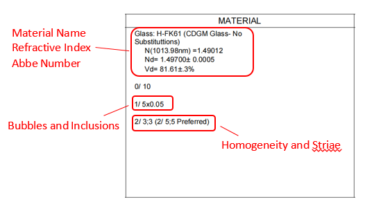
1/ : Bubbles and Inclusions
Usually written as 1/AxB where
A is the number of allowed bubbles or inclusions in lens
B is the length of side of a square in units of mm
2/ : Homogeneity and Striae
Usually written as 2/A;B where
A is the class number for homogeneity
B is the class for striae
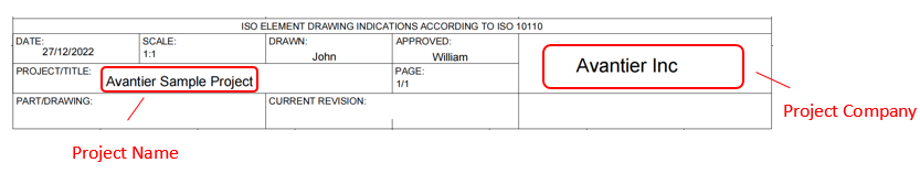
Field 3: Title Field
The last field on an optical drawing is called the title field, and it is here that all the bookkeeping happens. The author of the drawing, the date it was drawn, and the project title will be listed here, along with applicable standards. Often there will also be room for an approval, for a revision count, and for the project company. A final crucial piece of information is the scale: is the drawing done in 1:1, or some other scale?
Now you know how to read an optical drawing and where to find the information you’re looking for. If you have any other questions, feel free to contact us!